 Call:
Call:414-327-1555
Fax : 414-327-0577
Email: indelect@execpc.com
Catalog, Quote, Availability.
Call:
|
Setting up the GMM™ Using the GMM IntroductionThe 860 Series of Graphical MultiMeters (GMM) are state-of-the-art multimeters that use graphical features to display measurement information. One of those graphical features is TrendGraph. TrendGraph plots measurement data over a selected time period. The GMM can plot AC and DC voltage amplitude, AC and DC current amplitude, AC signal frequency, and ohms. Not only does the GMM display the plotted data, but it outputs data to a printer or a personal computer as well.
The TrendGraph feature is useful whenever you want to monitor a GMM measurement over time. Some typical monitoring applications are: line voltage for sags and surges, load center current, battery charging and discharging cycles, temperature changes, frequency changes and intermittent continuity to name just a few.
This application note describes the TrendGraph feature and how to use it in actual measurement situations.
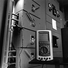
Setting Up the GMMConnect the GMM to the circuit and select the appropriate function for the measurement desired. For example, plotting the current drawn from one phase of an outlet load center, requires an AC current probe. The current probe steps down the load center current to a range within the GMM's measurement capabilities. Connect the current probe's output between the GMM's COM and mA/mA jacks. Select the mA/mA function and clamp the current probe around the load center wire or bus bar.
The range and wavescale settings determine the scale of the graph's vertical axis. Changing the wavescale adjusts the vertical scale to 25%, 50% or 100% of the range setting. Adjust these controls for an on-scale reading before setting up the trend mode.
Selecting the Trend ModeTrend is one of four GMM display modes. To select the Trend mode:
The plot graph appears in the window display area of the GMM. In addition, the five blue softkeys change to trend control functions.
Setting the Time IntervalThe time between plot points (time interval) is adjustable from 1 second to 15 minutes. This range makes it possible to display from 2 minutes (120 seconds) to 30 hours across the entire graph. For reference, the horizontal axis has a hash mark or division every tenth time interval.
The Time Longer (2) and Time Shorter (3) softkeys adjust the time between each plot point. There are 12 time interval settings in trend mode: 1, 2, 5, 10, 15, 30, 45 seconds and 1, 2, 5, 10, 15 minutes. Each time change clears and restarts the trend graph. The 1 second time interval is not available when plotting frequency.
To the right of the graph, the GMM displays the time per sample and the total graph time. Above the graph (as time/division), the time between hash marks (10 time intervals) is displayed.
Setting Trend TypeThe plotted data points can represent one of three data types: sampled, average, or high/low. The Trend Type softkey (4) selects the data type.
The Sampled data type selection places a data point on the graph that represents the latest measurement taken by the GMM. In other words, the plotted data point is equal to the digital reading displayed at that moment.
The Average data type selection places a data point on the graph that represents the average of all measurements taken by the GMM since the previous data point. Although this measurement may seem identical to the average reading used in the GMM's MIN MAX mode, it is different in that the readings are averaged for each plotted data point instead of over the entire trend time.
The High/Low data type places a vertical bar on the plot for every data point. The bottom end of the vertical bar represents the lowest sample measured since the previous data point and the top end represents the highest sample. The GMM clears the minimum and maximum data registers after each data point plot and uses a new set of MIN MAX data for the next data point. This selection captures any large changes that occur during the time interval.
Using the GMMDisplaying a TrendGraphIn TrendGraph mode, the GMM plots 120 points of measurement data on a graph in the window display area of the GMM. When a measurement is added, the plot points already on the graph shift one plot point to the left, and the GMM places the new measurement at the right end of the graph. This action makes the graph appear to "walk" toward the left, just like chart paper coming out of a strip chart recorder. The data point shifted off the end of the graph is gone from the GMM's memory.
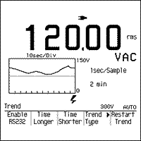
The value measured by the GMM is represented by the placement of the plot point on the graph's vertical axis. The relative time of the measurement is represented on the horizontal axis. The time an event occurred can only be related to other plot points on the graph. Figure 1 shows a typical TrendGraph display.
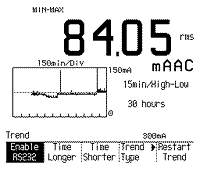
Figure 2 is an actual example of a High/Low trend plot of current drawn from a load center supplying power to a building's AC outlets.
While plotting the load center's current, the GMM's MIN MAX mode was also running in the background. The timer information displayed next to the minimum and maximum values, is used to determine the actual time of day the load center's minimum and maximum load occurred.
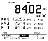
Figure 3 shows the MIN MAX data taken during the load center current plotting. To calculate the time of day the two events occurred, simply add the timer values to the time of day the MIN MAX mode was started. Using the data from Figure 3 and a start time of 9:30 A.M., the minimum load was at 4:08 P.M. and the maximum load occurred at 6:31 A.M.
Tracking Continuity GlitchesSelecting trend view in the Ohms function causes an additional softkey selection to appear over softkey no. 4: Normal/Glitch. When in Normal, the TrendGraph mode operates as explained above. The Glitch selection adds a narrow band under the horizontal axis of the plot area. In this "glitch" area of the plot, vertical marks indicate where fast-occurring changes in continuity occur.
Each GMM resistance range has a predetermined trip point that enables or disables the continuity beeper. Table 1 lists the trip values for the 860 Series Graphical Multimeter.
With glitch mode enabled, these same trip points are used to detect a continuity glitch. The GMM places a vertical bar in the glitch area of the plot when the measured resistance goes from high to low, or low to high across the trip point in less than 25 miliseconds. Gradual changes through the trip points will not trigger the glitch indication.
Storing Screens and ConfigurationsThe TrendGraph and other display data can be stored, printed, or downloaded to a PC. To store displayed information (867B only):
Storing the screen only captures an image of what is within the confines of the display. This is analogous to placing a camera on the display and snapping a picture.
To download the GMM screen data to a PC, you will need the FlukeView 860 software. Refer to the software user's manual for setup, connection, and downloading instructions.
To speed up the setting of the range, trend type, and time interval, you can save the GMM configuration settings as follows:
To recall the configuration:
The Load Config softkey will only appear when the function selected by the rotary switch is compatible with the highlighted configuration.
Outputing Trend DataIf more trend data detail is required, the GMM's optically isolated RS-232 interface sends out actual measurement data to a printer or a PC. When connected to a PC running FlukeView 860 software, all data for each plot point is sent to the PC and recorded in memory. The amount of data collected is only limited by the amount of available memory in the PC.
You can create printed hard copy listings of the trend data as follows:
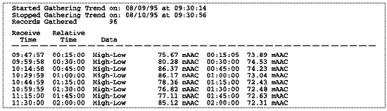
Figure 4 contains a sample of the trend data collected on a PC for the load center example used in this application. Each line of the printout contains the real time (PC clock) the data was output, the elapsed time, the trend data type, the maximum reading, and the minimum reading. The elapsed time is the accumulated time since starting the trend mode.
While sending ohms trend data out the GMM's serial port with the glitch mode enabled, the text "Discon" (Discontinu-ity) appears in a column between the trend type label (Sample, Average, or High-Low) and the ohms value to indicate an ohms glitch.
The trend data captured with the FlukeView software can be imported into a spreadsheet for further analysis, brought into a report, or archived for future reference.
Printing ScreensThe plotted graph along with other display data can be printed directly to a printer or sent to a PC for inclusion with reports. To print the display, first review the "Printing" section of the 860 Users Manual, which describes how to properly setup the printer and connect it to the GMM. To print a screen on a properly connected printer:
The screens used in this application note were imported from an 865 using the FlukeView 860 software. Refer to the SW860 FlukeView Software Users Manual for proper setup and operation.
Tracking Long Term TrendsSetting up the GMM to track data for longer than 6 to 10 hours requires the use of the battery eliminator. Typically the NiCd battery pack provides up to 10 hours of operation while a set of alkaline batteries may only last 6 hours.
By connecting your GMM to an appropriate power source through the battery eliminator, you can collect data indefinitely. Although the maximum GMM display is 30 hours, a GMM downloading trend data to a PC could go for a much longer period of time.
Other Trend ApplicationsUsing the GMM with compatible Fluke accessories provides a variety of measurement capabilities beyond those contained in the meter alone. You can measure temperature, pressure, vacuum and AC power with the appropriate accessory.
Plotting temperature is possible by using either the 80T-150U Universal Temperature Probe, 80TK Thermocouple Module, or 80T-IR Infrared Temperature Probe. Each of these accessories fits a specific range and application environment criteria.
Plotting pressure and vacuum measurements is possible using the PV350 Digital Pressure Vacuum Module. The PV350 displays results in English (psig or inches Hg) or metric (kPa or cm Hg) units.
The 80i-kW Current/(kW) Power Probe converts a combined measurement of volts and current into one kilowatt reading. The Power Probe works on both AC and DC current measuring up to 330 kilowatts.
SummaryTracking signal fluctuations over time is easy with the TrendGraph feature. TrendGraph is just one of many functions built into the 860 Series Graphical MultiMeters. This six in one meter offers versatility and accuracy in tracking down complex problems in electrical and electronic circuits.
There are two models in the 860 Series: the economical 863 and the full-featured 867B. Both of the models will make the measurements mentioned in this application note. Contact your nearest Fluke representative for further information.
|
|
|
|
|
|
|
|
|
|
|
|
|
|
|
|
|
Call: 414-327-1555 Fax : 414-327-0577 Email: indelect@execpc.com Catalog, Quote, Availability. © 2007 Industrial Electronics By Ross LLC ©2003-2006 SEO by synscon.com Search Engine Marketing Company
|