 Call:
Call:414-327-1555
Fax : 414-327-0577
Email: indelect@execpc.com
Catalog, Quote, Availability.
 Call:
Call:

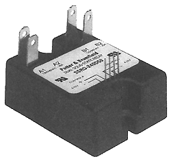
POTTER & BRUMFIELD SSRD series DUAL AC OUTPUT SOLID STATE RELAY File E29244 File E29244 UL Recognized for Canada · Two independent AC output solid state relays in one standard package. · Inverse parallel SCR outputs. · 25A rms & 40A rms versions available. · 3 - 32 VDC input control. · Zero voltage and random voltage turn-on versions. · 2500V rms optical isolation. · Quick connect style terminals. Form: 2 Form A (SPST-NO). Duty: Continuous. Isolation: 2500V rms minimum, input - output. Isolation Resistance: 10^10 ohms @ 500VDC minimum. Capacitance: 10 pf maximum (input to output). Temperature Range: Storage: -40"C to +120"C Operating Temperature: -25"C to + 80"C Case Material: Plastic, UL rated 94V-0. Base Plate Material: Ceramic. Case and Mounting: Refer to outline dimension. Termination: Refer to outline dimension. Approximate Weight: 3.5 oz. (98 g). Parameter Zero V Turn-on DC Input/AC Output Control Voltage Range Vin 3-32VDC 4-15VDC Must Operate Voltage Vin(op)(Max.) 3VDC 4VDC Must Release Voltage Vin(rel)(Min.) 1VDC 1VDC Input Current Input Current (Max.) 15mA DC 15mA DC 51K .jpg (780 pixels wide). HOW TO USE THESE CURVES Knowing maximum load current and maximum ambient temperature, use derating curves to determine the minimum required heat sink and maximum allowable base plate temperature. On left hand power dissipation curve, locate the point corresponding to maximum load current. Extend a line to the right from that point to the intersection of vertical line on right hand chart corresponding to maximum ambient temperature. From heat sink curve, read directly or extrapolate required heat sink size. Extend the line farther to the right and read on the right hand scale the maximum allowable base plate temperature. Thermal Derating Curves (70K .jpg 780 pixels wide). HEATSINK DIMENSIONS: · We recommend that solid State Relay Modules be mounted to a heatsink sufficient to maintain the module's base temperature at less than 85 degrees C under worst case ambient temperature and load conditions. · The heatsink mounting surface should be a smooth (30-40 micro-inch finish), flat (30-40 micro-inch flatness across mating area), un-painted surface which is clean and free of oxidation. · An even coating of thermal compound (Dow Coming DC340 or equivalent) should be applied to both the heatsink and module mounting surfaces and spread to a uniform depth of .002" to eliminate all air pockets. · The module should be mounted to the heatsink using two #l0 screws. The mounting screws should be torqued to 10 inch-pounds by alternately tightening the screws one quarter turn at a time. (approx. 22K .gifs @ 750 pixels wide). BUILD YOUR OWN PART NUMBER: A 24K graphic (GIF) of Ordering Information. This information will 'build' a part number from a list of available specifications. |
 |
Call: 414-327-1555 Fax : 414-327-0577 Email: indelect@execpc.com Catalog, Quote, Availability. © 2007 Industrial Electronics By Ross LLC |